Guide/Loop Filters
A loop filter is a useful construction pattern that allows one to reliably and flexibly filter gases or liquids by composition, temperature, or germ count, at low-to-no power cost.
Power-Free Valve Method
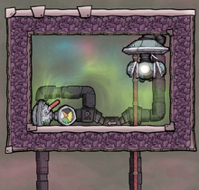
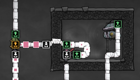
A valve-based gas loop filter.
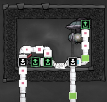
Ventilation overlay.


This loop filter method can be used to filter gases or liquids by type only (for other filter criteria such as temperature or germs, see the second method, below). It uses a Gas Valve (or a Liquid Valve) attached to a loop of pipes filled with only one type of gas/liquid, with an overflow line. This method has zero power draw, relying only on pipe mechanics to separate gases/liquids by type. The examples used here are for gases, but work equally well for liquids.
Input gases attempt to enter the loop via a Gas Bridge, and due to the bridge's priority mechanics (see Piping) and the fact that the loop is full of small packets of only the chosen gas type, other types of gas will be unable to enter the loop - but the chosen gas type will enter the loop, whereafter it will pass across the valve and through the overflow line.
The valve is set to the minimum non-zero setting of 0.1 g/s. This allows the loop to accept incoming gas flow of up to 999.9 g/s: if it ever receives a packet larger than 999.9 g, then 0.1 g will pass unfiltered through the input line. If packets of that size are expected (e.g. if filtering gases from a Gas Reservoir or from two or more Gas Pumps), adding a second gas bridge can help to capture more gas, reducing the likelihood of unfiltered gas on the input line - although it will still be unable to handle a constant stream of 1 kg/s of the filtered gas type.
If a flow rate of 1 kg/s of the filtered gas type is needed, a second valve-loop filter like this can be built and chained off of the input line in the same fashion. This can also be done to filter additional types of gas - one filter per gas type.
Setup Instructions
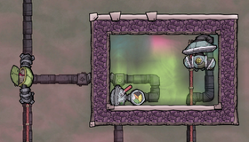
Step 1: The input and output lines are disconnected from the loop.
Step 2: A temporary supply line is providing gas to the loop only of the chosen type.
Step 3: The gas is backing up in the temporary supply pipes, indicating the loop has been primed. Now the temporary pipes can be disconnected and the input/output pipes can be connected.


The valve loop must be carefully primed before it can be used as a loop filter. The instructions for doing so are simple:
- Disconnect the loop from its overflow line, and disconnect the input line from the loop (or ensure that no gas can enter from the input line while priming). Ensure that the gas valve is set to the proper setting of 0.1 g/s.
- Pump in a supply of the chosen type of gas, bridging onto the valve loop as depicted above. This can be done using a temporary Gas Filter if needed, or it can be omitted if a stable supply (i.e. only the chosen gas type) can be provided. Only a small amount of gas is needed.
- Once the temporary supply line begins backing up (as depicted above), the temporary line can be disconnected from the loop (and deconstructed if desired). Then just reconnect the loop to its overflow line, then connect the input line to the loop. The loop filter is now primed and ready to use.
Advantages
- Efficiency - These filters do not draw power during regular operation, making proper Gas Filters or Liquid Filters (with their constant 120W draw) obsolete and even beating shutoff-based loop filters (which draw 10 W per shutoff)
- Resources - No Refined Metal is required for building this style of loop filter (only 50 kg of Metal Ore per valve), although Steel and Thermium are options if high-temperature operation is required
- Flexibility - The placement and quantity of the input bridges can be adjusted as needed, as can the size and shape of the filter loop
- Expandability - Several of these filters can be chained off of one input pipeline to be able to filter multiple different gas types (and/or to increase the maximum quantity that can be handled)
- Availability - The only research required to build this style of loop filter is Pressure Management, optionally with Filtration if a gas filter is needed during setup, neither of which require any Advanced Research
Disadvantages
- Size - Although the loop can be safely made smaller, and the setup can be further condensed by repositioning the input bridge, the minimal size is still roughly 2x3 (of which a 1x2 area cannot be hidden, due to the gas or liquid valve)
- Capacity - A single filter of this type cannot handle filtering a constant supply of 1 kg/s of the filtered gas/liquid (although additional bridges can handle infrequent 1 kg packets), requiring additional filters to handle that amount of flow
Powered Shutoff Method

This loop filter method uses several Gas Shutoffs, each linked to a sensor immediately before it and leading into an output Gas Pipe, to pipe out the packet of gas (or liquid) that satisfies the sensor's criterion, or loop it back if it satisfies none (a situation that should be avoided) or the appropriate output pipe is blocked or backed up.
The input and output Gas Bridge are important in this construction, since they set the direction of flow (counterclockwise in this example) and priority (the contents will loop first before taking more input in).
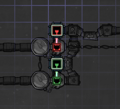
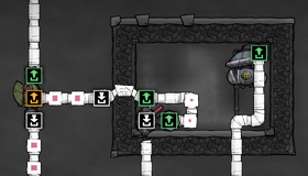
Automation overlay.
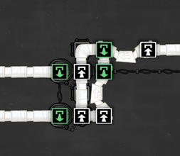
Ventilation overlay.
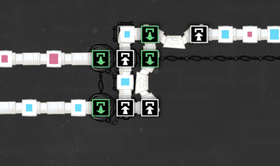
Filter in action, sorting a mixture of oxygen and hydrogen.


Advantages
- Efficiency - These filters take a minuscule amount of power at 10 W per shutoff currently triggered, essentially making proper Gas Filters or Liquid Filters (with their constant 120W draw) obsolete
- Versatility - They can filter based on anything for which a sensor exists instead of just gas or liquid type such as temperature or germ count
- Flexibility - Rather than be limited to the shape of existing filters, inputs and outputs can be placed where they best fit
- Expandability - Instead of selecting one gas or liquid and passing all the rest along, a sequence of options can be handled in the same loop
Disadvantages
- Size - They are somewhat large with their 3x4 size (of which the 2x4 sensor/shutoff block can't be hidden behind buildings).
- Cost - They take at minimum 170 kg of Refined Metals to set up (20 for auto wire, 100 for shutoffs, 50 for sensors)
- Power - While 10 W per shutoff is very small, it is still a nonzero cost
- Availability - To build the components requires HVAC for gas filtering, Liquid Tuning for liquid, Healthcare for germ versions of either and Generic Sensors for the NOT gate, all of which are advanced research.
Variations
A-!A

Using the same setting on both sensors, but preceding one with a NOT gate. This lets one element through pipe A and everything else through pipe B, essentially recreating the Gas Filter or Liquid Filter.
Multi-output
Using more than two sensor+shutoffs to sort out the input. Note that you need to make sure that you have as many outputs as the amount of gases the input consists of.
Usage
Gas or liquid sorting
Sort out mixed sources of gas or liquid.
Filtering station
A centralized gas filtering station somewhere in your base will get rid of the pesky packets of Chlorine, Hydrogen, Natural Gas and so on that you have floating around.
Atmosphere adjustment
Fill the room with a specific gas or gas mixture far faster by simultaneously piping the needed gas in through a vent while using a Gas Pump to take the existing mixture and filtering it to pump the needed gases back in.
Disinfection
A liquid reservoir that's situated in a Chlorine atmosphere destroys germs in its liquid, but not instantly. Pipe it back into the tank if the germ count is above zero.
Refinery Coolant
Coolant piped out of the Metal Refinery can be piped back in if it's cold enough, or piped out to get processed (polluted water into water sieve, crude oil into oil refinery or oil cooker, petroleum into plastic or power) or cooled down.