Guide/Automation
Automation is an important part of almost any base in Oxygen not Included. From opening Bunker Doors to turning off Coal Generators, it can help protect a base and conserve (scarce) resources. Although Automation may seem overwhelming at first, it is relatively easy to understand if approached correctly. This is the goal of this guide.
Signals and Wires
There are two Automation signals: Green and Red. They can also be seen as On and Off or 1 and 0, depending on what you prefer. Everything with an Automation Output always outputs one of these two signals.
Automation Wire is the basic way of transferring these Automation signals. Similarly to Wire, it transfers them instantly and not in packets, like Liquid Pipes and Gas Pipes. Networks made from Automation Wires also have a state; either Green or Red. The state of the Automation Wire will be red if nothing outputs a Green signal. However, if anything outputs a Green signal, the Automation Wire's state will be Green. Automation Wire Bridges work just like normal Automation Wire, only that they allow the crossing of two wires without them connecting.
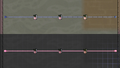
All Signal Switches connected to the wire send a red signal, so the wire is red.
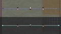
Now one of three sends a green signal: The wire is green too.
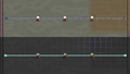
With all three switches sending a green signal the wire is green.


Ports
For a list of all buildings with Automation Inputs and Outputs see: Outputs Inputs
Outputs
An ![]() Output port adds a signal to an Automation Wire (see Signals and Wires). These can be found on Sensors and some other buildings, mostly storage ones. Everything with an Output port allows Automation interaction with whatever the port belongs to. They are visible in the Automation Overlay and, when hovered over, display when they'll send a Green signal and when a Red one.
Output port adds a signal to an Automation Wire (see Signals and Wires). These can be found on Sensors and some other buildings, mostly storage ones. Everything with an Output port allows Automation interaction with whatever the port belongs to. They are visible in the Automation Overlay and, when hovered over, display when they'll send a Green signal and when a Red one.
Inputs
An ![]() Input port gets affected by what signal it receives. It lets Automation control whatever it belongs to. For example, it can turn on a Petroleum Generator. It too can be seen in the Automation Overlay and, when hovered over, displays the effect of a Green or a Red signal on the building it belongs to.
Input port gets affected by what signal it receives. It lets Automation control whatever it belongs to. For example, it can turn on a Petroleum Generator. It too can be seen in the Automation Overlay and, when hovered over, displays the effect of a Green or a Red signal on the building it belongs to.
Ribbon Outputs
These ports allow writing to Automation Ribbon, and only appear on Ribbon Writers.
Ribbon Inputs
These ports allow reading from Automation Ribbon, and only appear on Ribbon Readers.
Reset Ports
Reset ports appear exclusively on Memory Toggles and Signal Counters. They are used to reset their memory.
Control Ports
Control ports are used to select from which input Signal Selectors will read a signal and to which output Signal Distributors will write a signal.
Basic Input and Output ports are the most important ports for simple Automation while the other ports only come into play if Automation control gets more complex.
Automation Ribbon
Automation Ribbon works like four Automation Wire in the same place. This allows compacting Automation networks if necessary. Automation Ribbon Bridges can be used to cross two Ribbons without connecting them. Note that Automation Ribbon should not be connected to Automation Wire to prevent Signal Overload Damage.
Using Automation Ribbon
To get a signal onto Automation Ribbon, a Ribbon Writer needs to be used. It can be set to write to one of the four Bits of the Ribbon. For example, if a Writer receives a green signal, and is set to write Bit 1, the connected Automation Ribbon will become green in Bit 1. A Ribbon Reader can then be used to get the signal back "out of" the Ribbon. It can be set to read from one Bit. If that Bit is green, a connected Automation Wire will be green too.
Automation Buildings
Sensors
Sensors allow interaction of Automation and the environment they are in. Most Sensors can be set up to output a green signal whenever a specific condition is met, while this is not possible with others. For more information on each Sensor, see their specific page.
Logic Gates
Logic Gates can be used to let signals interact with each other to create more complex Automation. For a summary of Logic Gates, see the above page.
Interaction
These buildings allow Automation to affect the environment back:
- Automated Notifiers create a message whenever they receive a green signal that appears in the top left of the screen.
- Hammers make a sound if they are set up to hit a building whenever they receive a green signal.
- Duplicant Checkpoints can allow or deny access to an area, depending on the signal they receive. Unlike doors, Duplicants will wait in front of one if their current Errand needs them to pass one.
Multiplexing
For non-programmers understanding the Multiplexing components can be confusing.
Basically it's like a ribbon cable in that it lets you have more "status pipes" on fewer squares, but with the change that you can only access one at a time
In their simplest form multiplex devices are like walkie talkies that you can pick a channel to listen and/or speak on, and switch channels without having to rewire everything.
In more advanced modes they can be used to dynamically link two different channels together like how old school telephones worked
Or they can be used to cycle through all channels in response to a trigger (like checking on each of your rooms once per cycle, or a home base checking in on the status of systems at a remote base)
You can even add Time based multiplexing (ex. by adding a clock signal using a Timer) to allow the exchange of large amounts of data on very few cables
For more details you can take a look at the Multiplexing Guide
Practical Automation
Edge / Flank detection
Sometimes you need to generate a signal when a condition changes but don't want that signal to continue while the situation remains.
For example you might want briefly turn on a lamp when the temperature exceeds 100 °C.
This is where edge / flank detection comes in.
Rising edge detection
This can be accomplished by splitting the input signal into two lines. One line goes directly to an AND gate, the other line goes through a filter and a NOT gate before going into the AND gate. The result is that when the input signal turns to ON the output signal at the AND gate will also turn to ON but will turn off after the filter gate time has elapsed.

Falling edge detection
This can be accomplished by splitting the input signal into two lines. One line goes through a buffer gate and into an AND gate. The other line goes through a NOT gate and into the AND gate. The result is that when the input signal turns to OFF the output signal of the AND gate will turn to ON but will turn off after the buffer gate time has elapsed.
